DESCRIPTION
Brake system is hydraulically operated, utilizing a tandem master cylinder and power brake unit. Front disc brakes consist of rotors attached to wheel hub and drive shaft and two piston calipers attached to strut assembly. Disc pads are equipped with a ceramic transmitter-type wear sensor. Transmitter is mounted on cross spring and will break when contact is made with pad plates, interrupting control circuit and causing indicator light on instrument panel to be activated. All models are equipped with pressure regulator that is mounted to body and operated by a spring connected to rear axle. Rear brakes are leading-trailing shoe/drum type, using a dual piston wheel cylinder. Parking brake is cable actuated, operating secondary shoes of rear brake assemblies.
ADJUSTMENT
NOTE - Adjustments or readjustments should be carried out on cold brakes. However, brakes must be warm when testing. Instrument panel trim must be removed to adjust master cylinder push rod free play.
MASTER CYLINDER PUSH ROD FREE PLAY
Adjustment of piston rod play at master cylinder is made by loosening lock nut and turning piston rod until correct free play, measured at brake pedal, is obtained. When correct free play of .039" is obtained between push rod and piston, free play is measured at brake pedal will be approximately .2".
FRONT DISC BRAKES
Front disc brakes are self-adjusting, therefore, no adjustment in service is required.
REAR DRUM BRAKES
Raise and support rear of vehicle and release parking brake. Using a 17 mm wrench, tighten eccentric adjusters until wheels can no longer be turned by hand. Loosen eccentric adjusters until wheels are just fee to turn.
PARKING BRAKE
NOTE - Because of the residual pressure in brake regulator, the right rear brake shoes might not fully release from drum. Before adjustment, move lever on pressure regulator rearward.
Raise and support rear of vehicle and adjust rear brakes. Lift parking brake lever until it engages third ratchet stop. Adjust nut at equalizer until rear wheels are just free to turn. When parking brake lever is pulled up one additional notch (to fourth ratchet stop), rear wheels should be locked.
BRAKE PRESSURE REGULATOR

2) Raise vehicle on a hoist and make measurement again. If there is a difference in measurements, adjust by turning clamps. See Fig. 1.
3) Connect pressure gauges to left front and right rear wheels. Bleed pressure gauges. Apply pressure to foot pedal and note reading at gauge. Repeat procedure on right and left rear wheels.
Brake Pressure Values
Application Pressure (psi)
Left Front............................................. 700
Right Rear............................................. 475-625
Right Front............................................ 1400
Left Rear.............................................. . 765-945
NOTE - DO NOT adjust brake pressure regulator when pressure is applied to brake pedal.
4) If pressure at rear wheels is to high, release spring and move spring support arm forward. If pressure at rear wheels is too low, move support arm rearward.
HYDRAULIC SYSTEM BLEEDING
Fill master cylinder reservoir with brake fluid and maintain level throughout bleeding operation. Attach a hose to bleeder screw, and immerse opposite end in a container partially full of brake fluid. Open bleeder screw, approximately one-half turn, depress brake pedal, close bleeder screw, and slowly return pedal. Continue operation until air bubbles are no longer seen in discharged fluid. Bleeding sequence is left-rear, right-rear, right-front, left-front.
REMOVAL & INSTALLATION
FRONT DISC BRAKE PADS
Removal - Remove lock clips. Pull out retaining pins so they project into openings in side members. NOTE - Do not remove rubber grammets from side member holes. Using a suitable extractor tool (SB-3), remove disc pads from caliper.
NOTE - Disc pads can be removed on right side only after removing front exhaust pipe.
Installation - Press both pistons into caliper bores.
NOTE - Fluid level in master cylinder reservoir will rise. Siphon sufficient fluid to prevent reservoir from overflowing. Ensure pistons are in correct alignment in bores using suitable tool (B-5). Install disc pads in recesses of caliper, slide in retaining pins, and install lock clip. Pump brake pedal several times to position disc pads. Bleed hydraulic system if necessary.
FRONT DISC BRAKE CALIPER
Removal - With wheel and tire removed, take out disc pads. Disconnect hydraulic line from caliper. Remove bolts securing caliper and take off caliper.
Installation - To install brake caliper, reverse removal procedure and bleed hydraulic system
FRONT DISC BRAKE ROTOR
Removal - With wheel and tire assembly removed, take off caliper. Do not disconnect hydraulic line unless necessary. Remove screw retaining rotor to wheel hub (if equipped) and withdraw rotor.
Installation - To install rotor assembly, reverse removal procedure and bleed hydraulic system.
REAR BRAKE DRUM
Removal - Raise and support vehicle, remove wheel and tire assembly. Pry off dust cap, remove cotter pin from hex nut, and remove nut. Remove brake drum making sure that retaining washer and wheel bearing do not fall out.
Installation - To install, reverse removal procedure, adjust brakes, and adjust wheel bearings. See Wheel Bearing Adjustment in WHEEL ALIGNMENT Section.
REAR BRAKE SHOES
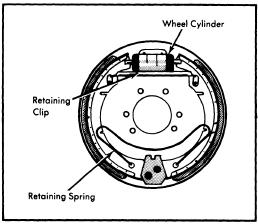
Removal - With brake drum removed, remove retaining spring for brake shoes. Remove shoes as an assembly by disconnecting spring at bottom, pulling shoes back from wheel cylinder, and disconnecting parking brake cable.
Installation - To install, reverse removal procedure and note the following: Make sure long ends of retaining clip and spring are installed on secondary shoe and parking brake lever. Ensure brake shoes are correctly positioned on wheel cylinder pistons.
REAR BRAKE WHEEL CYLINDER
Removal - With drum and shoes removed, depress pedal approximately 1.2" and hold in position using a suitable pedal support. Disconnect hydraulic line from rear of backing plate and plug line to prevent loss of fluid. Remove retaining screws and wheel cylinder.
Installation - To install, reverse removal procedure, adjust brakes and bleed hydraulic system.
MASTER CYLINDER
Removal - Disconnect hydraulic line at rear of master cylinder. Depress brake pedal 1.2-1.6" and hold in position using a suitable pedal support. Disconnect remaining hydraulic line and cylinder mounting nuts. Separate master cylinder from power unit taking care not to lose "O" ring installed betweend them.
Installation - To install, reverse removal procedure and bleed hydraulic system.
POWER BRAKE UNIT
Removal - Siphon brake fluid from master cylinder reservoir and disconnect hydraulic lines. Loosen hose clamp and disconnect vacuum hose from power unit. From inside vehicle remove trim below instrument panel as necessary. Disconnect push rod from brake pedal, remove power unit adapter attaching nuts, and remove power unit and master cylinder from engine compartment as an assembly. Separate master cylinder and adapter from power unit.
Installation - To install, reverse removal procedure and note the following: Be sure to install "O" ring between master cylinder and power unit. Install adaptor to power unit so that center punch mark on adaptor is located on lower right side facing engine. To complete installation, adjust pedal push rod free play and bleed hydraulic system.
Check Valve Replacement - A vacuum check valve is located in vacuum line between intake manifold and power unit. To remove, loosen hose clamps, separate vacuum hoses from check valve, and remove check valve. To install, reverse removal procedure and note the following: Check valve stamped with the word "MOTOR" and a arrow. End of valve in which arrow points must be connected to shorter hose from intake manifold.
OVERHAUL
FRONT DISC BRAKE CALIPER
Disassembly - Remove disc pads. Pry out retaining ring and remove dust seal by hand. Place a small block of wood in caliper cavity, and remove piston by applying compressed air to fluid inlet. Remove remaining piston in same manner. Remove seal from caliper bore using a piece of wood or plastic. NOTE - Do not use hard or sharp tools for this purpose. Do not separate caliper halves.

Cleaning & Inspection - Clean all parts in alcohol only. Check cylinder bore and piston
for damage. NOTE - Do not machine caliper bore or piston. Parts are serviced by replacement only.
Reassembly - Coat all parts with ATE brake cylinder paste (or equivalent), reverse disassembly procedure, and note the following. Use new seals, dust boots, and retaining rings when reassembling. When installing piston, make sure machined surface of piston face makes a 20 degree angle to wall of caliper bore (see illustration). Install disc pads after caliper has been installed on vehicle.

REAR WHEEL CYLINDER
Disassembly - Thoroughly clean outside of cylinder. Remove end caps, piston and seal assemblies, and spring. Remove dust cap and bleeder screw.
Cleaning & Inspection - Clean all parts in alcohol only. Check all parts for rust, corrosion, or other damage. Check cylinder bore and piston for wear. Maximum allowable cylinder diameter is .6287; minimum allowable piston diameter .6197". Manufacturer recommends replacing rubber components each time cylinder is disassembled.

Reassembly - Reverse disassembly procedure and not the following: Apply a thin coat of ATE brake cylinder paste (or equivalent) to all parts during assembly.
MASTER CYLINDER
Disassembly - Thoroughly clean outside of master cylinder. Remove hydraulic fluid reservoir, remove retaining ring, and remove primary piston assembly. Loosen or remove (if necessary) piston stop screw and remove secondary piston assembly. Disassemble primary and secondary piston assemblies.
Cleaning & Inspection - Clean all parts in alcohol only. Dry all parts with compressed air and check that compensating parts of cylinder are free of obstructions. Check cylinder bore and pistons for rust, corrosion or other damage. Inspect cylinder bore and pinion for wear. Maximum allowable cylinder diameter is .817:; minimum allowable piston diameter is .807". Manufacturer recommends replacing all rubber parts whenever cylinder has been disassembled.
Reassembly - Reverse disassembly procedure and note the following: Do not apply grease to push rod as damage may result to rubber components.
POWER BRAKE UNIT
NOTE - Manufacturer does not recommend overhaul of power brake unit.


1 comments:
Great blog post.. very valuable information.
we're committed to helping you ease some of your stress by bringing your vehicle back to its pre-accident condition. We're an MPI-accredited collision repair shop providing complete automotive collision repair services for all kinds of cars, including hybrid cars, so you can get back to your routine in no time.
Cheap Vehicle Repair Winnipeg
Windshield Repair Winnipeg
Post a Comment